
 The 12AX7 pinout is shown here. There are 2 independent triodes, 2 plates, 2 grids and 2 heaters. Only the ground wire between the heaters is shared. This results in a 9-pin tube. The 12AX7 pinout is shown here. There are 2 independent triodes, 2 plates, 2 grids and 2 heaters. Only the ground wire between the heaters is shared. This results in a 9-pin tube.Here is the rundown: Plates: 1, 6 Grids: 2, 7 Cathodes: 3, 8 Heaters: 4, 5 Ground: 9 | |
STEP 1: Tube Socket Wiring  The cathode resistors and 10uF decoupling cap are wired directly to the tube SOCKET - make sure you have a socket and do not try to solder to the tube legs. The cathode resistors and 10uF decoupling cap are wired directly to the tube SOCKET - make sure you have a socket and do not try to solder to the tube legs.Here is a diagram showing the tube socket turned upside down with the tube going into the page. Wire the circuit right at the tube sockets with elements very close to the tube legs. | |
STEP 2: Wire all the 12V pins  The 2 plates and 2 heater pins are all connected to the +12V line. Wire those first using resistor leads or the like. This means 4 of the 9 pins (almost half of them) are all simply connected together. The 2 plates and 2 heater pins are all connected to the +12V line. Wire those first using resistor leads or the like. This means 4 of the 9 pins (almost half of them) are all simply connected together. | |
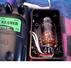
STEP 3: Wire the components  Next, add the 15k, 100k and 10uF decoupling cap. This image shows all three but the 10uF decoupling cap is tucked around the backside of the tube, using blue heat shrink tubing to insulate the legs. Next, add the 15k, 100k and 10uF decoupling cap. This image shows all three but the 10uF decoupling cap is tucked around the backside of the tube, using blue heat shrink tubing to insulate the legs.You can also see this cap in more detail in the image at the top of the page. This image shows the input and output wires too, but you don' t need to do that at this stage. You should now have the tube circuit and the PCB mods ready. Now its time to connect up the sub-circuits and to the final assembly. | |
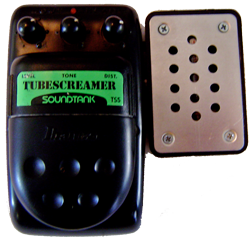
The Marriage of Tube and Screamer!
Although I chose the TS-5 for my Frankenstien, you can use any of the TS series.
|
|
The TS-5 is an excellent candidate because it is electronically identical to the TS-9, has an easy to drill plastic body with jacks mounted on the front rather than sides, and is generally very inexpensive. This mod is of my own design; I have not seen it anywhere else and this mod can be done to a variety of distortion boxes too.

The 12AX7 Tube
Subscribe to:
Post Comments (Atom)


1 comment:
I hope you don't mind, but I'm borrowing the tube setup for a different project. I have noticed, however, that you have the heater wired for 6v operation here. You need to disconnect pin 9, and run pin 5 to ground for 12v.
Post a Comment