
STEP 1: Re-route the power line The TS12AX7 will not run on a battery - the tube heaters would drain it quickly. You will reuse the battery wires as power supply lines for the sidecar and use the power supply adaptor for all power needs. Because the power adapter jack switches the battery out of the circuit, you need to re-route the red battery wire to the positive supply pin on the jack. Locate it (use a DVM if you need to) and re-locate the red battery wire. The TS12AX7 will not run on a battery - the tube heaters would drain it quickly. You will reuse the battery wires as power supply lines for the sidecar and use the power supply adaptor for all power needs. Because the power adapter jack switches the battery out of the circuit, you need to re-route the red battery wire to the positive supply pin on the jack. Locate it (use a DVM if you need to) and re-locate the red battery wire. | |
STEP 2: Locate the 4.7K input and 1k output resistors  First, find the 4.7k input resistor for the clipper circuit (in the red circle here) and replace with a 1k resistor if you want (see Schematics & Theory). First, find the 4.7k input resistor for the clipper circuit (in the red circle here) and replace with a 1k resistor if you want (see Schematics & Theory).Find the 1k resistor that connects the output of the clipper circuit to the input of the tone circuit. The tube sub-circuit is inserted between these two circuits. One end of the 1k resistor will connect to the output pin of the op amp, the other will connect to the input of the next stage. Lift the side of the resistor which connects to the output of the op amp. It is here in the blue circle. In the hole that is exposed, insert a 10uF polarized cap with the positive plate toward the op-amp output. This is the grey cap just to the left of the blue circle. The exposed leg of the cap will connect to the input tube circuit. The exposed leg of the 1k resistor will attach to the output of the tube circuit. | |
STEP 3: Add the 47k grid stopper resistor and 10uF output cap  The output of the clipper connects to the grid of the first half of the 12AX7 via a 47k resistor. That resistor is soldered directly to the clipper output cap. The output of the clipper connects to the grid of the first half of the 12AX7 via a 47k resistor. That resistor is soldered directly to the clipper output cap.The other side of the 1K resistor that was lifted in the previous step is connected to the output decoupling cap, another 10uF, with the positive plate of the cap connected to the 1K resistor and the other leg left flying. This gives 2 connection points for the tube circuit. | |
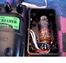
STEP 4: Add the wring  You must use shielded cable for this part. The end connecting to the PCB will have the shield clipped and tucked under heat shrink tubing. You can see both input and output wires here along with ample heat shrink tubing to insulate the components. You must use shielded cable for this part. The end connecting to the PCB will have the shield clipped and tucked under heat shrink tubing. You can see both input and output wires here along with ample heat shrink tubing to insulate the components. | |
The next step is to prep the tube circuit! | |
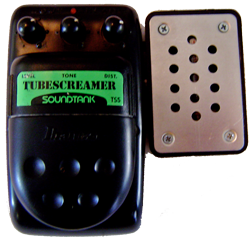
The Marriage of Tube and Screamer!
Although I chose the TS-5 for my Frankenstien, you can use any of the TS series.
|
|
The TS-5 is an excellent candidate because it is electronically identical to the TS-9, has an easy to drill plastic body with jacks mounted on the front rather than sides, and is generally very inexpensive. This mod is of my own design; I have not seen it anywhere else and this mod can be done to a variety of distortion boxes too.

PCB Modification
Subscribe to:
Post Comments (Atom)


2 comments:
can this be modified to have 2 9v wall inputs to power to power the pedal. I have an active bass and it uses 2 9v batteries. If so it could be powered by a 1 spot.
That would be overkill. There are a few more practical solutions to using two 9v wall adapters.
1. Use a 12v wall adapter.
2. If you really want to take a chance with18v--just use an 18v wall adapter. Yes, they do exist.
Post a Comment