
 Here is the modified Tube Screamer guts schematic. Click the image to enlarge it. The TS-12AX7 mods are shown in blue. Here are the design notes:
The Power supply has been increased to 12V. The TubeScreamer will run up to 15V by spec, but will probably get to 18V without a problem. The higher the voltage, the better. If you exceed 15V, do so at your own risk - you might destroy the 4558 op amp. Do not exceed 18V under any circumstances.
The 4.7k resistor on the inverting input of the clipper circuit has been lowered to 1k. This increases the gain almost five-fold for the clipping stage. The effect is subtle (and you can choose to ignore this part if you want) but it adds a bit more brightness.
The tube is a 12AX7 but any similar tube could be used (eg 12AY7). The tube is running at a super low plate voltage of 12V in a very non-linear operating area. The tube circuit is a cascaded pair of cathode followers. The voltage gain is 1.0 but the added clipping becomes highly asymmetrical.
The 3 added capacitors are all 10uF. These caps adjust the Low Frequency rolloff of the stage. To get LESS bass, DECREASE the values of the caps. To get MORE bass, INCREASE them. You can experiment with one, two or all three with varying amounts of bass increase or reduction. I prefer it very warm and bassy, but you might want something brighter.
The 100k and 15k resistors on the tube cathodes are the self-biasing resistors which set the operating range for each section. You can replace all or part of each resistor with a potentiometer to experiment with varying the bias point. Try not to exceed 6V on the second cathode. As designed, the bias voltages are around 2-3 volts.
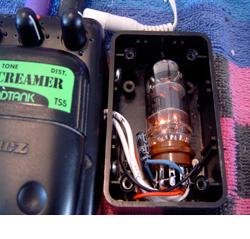
The 12AX7 Tube gets HOT! Be very careful because you can get a nasty burn. The heat is not from excess current, it is from the tube heaters, whose job is to heat the cathode.
There are 2 heaters which are each connected to the 12V supply line. Running the heaters at 12V cuts the heater current in half (from the other standard voltage, ~6.2V) so less current flows, but the heaters get hotter.
You must use shielded cable to implant the 12AX7 into the TS circuit. The lines need to be as short as possible and grounded on one end.
This is a really simple project that should only take you a couple of hours. However, if you do not have very much experience building, modifying or testing circuits, I suggest you get someone who knows how to do this stuff to make one for you.
And to the Tube-Purists: yes, I know its a 12V plate voltage and that is TOTALLY CHEATING as far as Tube Circuits go. And, I play pure-tube amps for a reason. Plus, as Cathode Followers, you get no gain from the tube. But after looking at several "boutique" designs selling for $300 and up, which use the same starved plate, I thought - what the heck - and I tried to preserve as much of the TS circuit as I could - only the 4.7k input resistor is changed in the actual circuit.
Finally, this circuit is still in design - I wanted to publish a mk I version that I could then add to and improve so check back for more improvements and tweaks.


1 comment:
Hey, why didnt you just re-house the entire pedal? or would that not be a good idea?
also, would it be wise to use heat paint(automotive engine enamel?)
Post a Comment